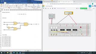
Media Summary: Find its Circuit Design (.brd file) to load in your project here: ... Note: The output of AND gate is connected to Common Anode. Boolean Expression: x=(A+B)*(B ̅+C) Truth Table: A B C x 0 0 0 0 ... In this video you will learn how to verify Truth Table of

Tinkercad Explained Building A 4 Bit Binary Adder - Detailed Analysis & Overview

Find its Circuit Design (.brd file) to load in your project here: ... Note: The output of AND gate is connected to Common Anode. Boolean Expression: x=(A+B)*(B ̅+C) Truth Table: A B C x 0 0 0 0 ... In this video you will learn how to verify Truth Table of

Photo Gallery

TinkerCad Explained: Building a 4-Bit Binary Adder
4 Bit Binary Adder Using TinkerCad
Demo: 4-bit Adder Subtractor using Full Adder IC with tinkercad
4-bit binary adder using tinkercad || simulation
#7 Four-bit Adder Logic Circuit using Tinkercad - Part 1
4-bit Adder and Subtractor Circuit Explained
FULL ADDER ON TINKERCAD
4 Bit Binary Adder || Digital Logic Design || Digital Electronics
Making and Simulating a simple computer in Tinkercad (4 - bit adder)
4 Bit Binary Adder Subtractor  || Digital Logic Design || Design Electronics
Learn how computers add numbers and build a 4 bit adder circuit
Tutorial | Building the 74283 74HC283 4 BIT ADDER
View Detailed Profile
TinkerCad Explained: Building a 4-Bit Binary Adder

TinkerCad Explained: Building a 4-Bit Binary Adder

Final project

4 Bit Binary Adder Using TinkerCad

4 Bit Binary Adder Using TinkerCad

4 Bit Binary Adder

Demo: 4-bit Adder Subtractor using Full Adder IC with tinkercad

Demo: 4-bit Adder Subtractor using Full Adder IC with tinkercad

4

4-bit binary adder using tinkercad || simulation

4-bit binary adder using tinkercad || simulation

In this video you will see how to make a

#7 Four-bit Adder Logic Circuit using Tinkercad - Part 1

#7 Four-bit Adder Logic Circuit using Tinkercad - Part 1

Learn how to design a

4-bit Adder and Subtractor Circuit Explained

4-bit Adder and Subtractor Circuit Explained

In this video, the

FULL ADDER ON TINKERCAD

FULL ADDER ON TINKERCAD

circuit #electronic #electroniccircuits #

4 Bit Binary Adder || Digital Logic Design || Digital Electronics

4 Bit Binary Adder || Digital Logic Design || Digital Electronics

DigitalElectronics #BinaryAdder #LogicDesign #4BitAdder #DigitalCircuits.

Making and Simulating a simple computer in Tinkercad (4 - bit adder)

Making and Simulating a simple computer in Tinkercad (4 - bit adder)

Find its Circuit Design (.brd file) to load in your project here: ...

4 Bit Binary Adder Subtractor  || Digital Logic Design || Design Electronics

4 Bit Binary Adder Subtractor || Digital Logic Design || Design Electronics

BinaryAdder #DigitalLogicDesign #ElectronicsDesign #BitAdder #CircuitDesign.

Learn how computers add numbers and build a 4 bit adder circuit

Learn how computers add numbers and build a 4 bit adder circuit

Let's

Tutorial | Building the 74283 74HC283 4 BIT ADDER

Tutorial | Building the 74283 74HC283 4 BIT ADDER

Please check out the updated Video: https://youtu.be/uAs63grX-lY.

Boolean Expression Implementation in Tinkercad

Boolean Expression Implementation in Tinkercad

Note: The output of AND gate is connected to Common Anode. Boolean Expression: x=(A+B)*(B ̅+C) Truth Table: A B C x 0 0 0 0 ...

4 Bit Adder Subtractor circuit simulation in Tinkercad using logic gates

4 Bit Adder Subtractor circuit simulation in Tinkercad using logic gates

This video is based on the simulation of

Experiment to verify truth table of Full Adder using TinkerCAD

Experiment to verify truth table of Full Adder using TinkerCAD

In this video you will learn how to verify Truth Table of

Experiment to verify Truth Table of Half Adder using TinkerCAD

Experiment to verify Truth Table of Half Adder using TinkerCAD

In this video you will learn how to verify Truth Table of

tinkercad 74HC283 adder

tinkercad 74HC283 adder

tinkercad 74HC283 adder